Graphite is available as a variety of different material forms, the most useful in the electronics cooling market being pyrolytic graphite, graphite fiber reinforced carbon and polymer matrix composites, graphite foams and, the subject of this brief, natural graphite. The basic structure of graphite is shown in Figure 1.
 |
Figure 1. Structure of graphite crystal.
The structure is composed of infinite layers of carbon atoms arranged in the form of hexagons lying in planes. The stacking arrangement is ABAB with atoms in alternate planes aligning with each other. Interlayer spacing is 3.354 angstroms and interatomic distance within the planes is 1.415 angstroms. The crystal density is 2.25 g/cm3.
The graphite crystal is one of the most anisotropic (meaning exhibiting properties with different values when measured along axes in different directions) bodies known. Anisotropy is the direct result of the layered structure with extremely strong carbon-carbon bonds in the basal plane (A and B planes in Figure 1) and weak bonding between the planes. Properties of graphite crystals illustrating this anisotropy are shown in Table 1. Of particular interest for the electronics cooling market is the very high basal plane thermal conductivity (~2000 W/mK) achievable in single crystal graphite.
Table 1. Properties of Graphite Crystals at Room Temperature
|

 .m
.mThe anisotropy of the single crystal is carried over in the properties of commercial graphite materials to varying degrees. Graphites can be made with a very wide range of properties and degree of anisotropy depending on the selection of raw materials and processing. For example, pyrolytic graphite, formed from the gas phase pyrolysis of hydrocarbons can exhibit thermal conductivity in the basal plane of up to 1700 W/mK and 10 W/mK perpendicular to the basal plane.
Pitch-based graphite fibers can achieve thermal conductivity parallel to the fiber direction of ~1000 W/mK. At the other extreme, polycrystalline graphite materials can be manufactured with almost isotropic properties, the thermal conductivity in this case being a rather uninteresting 100 W/mK!
Natural Graphite Products
For pyrolytic graphite and graphite fiber-based materials, very high temperatures (~3000oC) are required to develop the high thermal conductivity of interest to the electronics cooling market. These products have found application in high performance, niche aerospace applications but have not penetrated the telecommunications or computer markets by virtue of their high processing costs.
By contrast, natural graphite, a mineral form of graphite, has been graphitized “by nature”, and can therefore be manufactured into products without the need for high temperature processing. In addition, the manufacturing processes used to produce the material are so versatile that both thermal interface sheet material (Figure 2) and heat spreader/sink components (Figure 3) can be produced from the same raw materials. These materials retain the thermal anisotropy features of single crystal graphite, with control of thermal anisotropy being possible by manipulation of the processing.
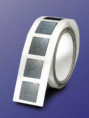 |
Figure 2. Edge-sealed natural graphite thermal interface material.
The material is attractive as a thermal interface material because of its combination of good surface conformability and high thermal conductivity. The thermal anisotropy can be varied, as demonstrated in Table 2, for commercially available eGraf™ thermal interface materials.
Table 2. Thermal Conductivity Values for Commercially Available Natural Graphite Thermal Interface Materials
|
The high in-plane thermal conductivity results in spreading and evening out of the hot spots resulting from uneven loading, surface distortion and uneven heat distribution on the die surface. To exploit the high in-plane thermal conductivity of graphite, thermal engineers have begun to look at the concept of applying the thermal interface to the entire base of the heat sink, rather than just to the die.
Recent developments have included the development of insulating plastic films on the surface of the graphite and edge protection schemes to eliminate any concerns of flaking of electrically conductive graphite particles.
Heat spreader and heat sink materials derived from natural graphite are a relatively recent development. Lamination, molding and embossing methods can be employed to produce a variety of different component forms as shown in Figure 3.
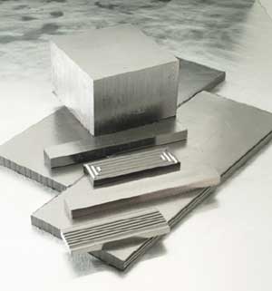 |
Figure 3. Natural graphite heat spreader components.
As with thermal interface materials, the thermal anisotropy can be varied. Thermal conductivity values of 400 W/mK and 7 W/mK have been measured for in-plane and through thickness directions, respectively. The density of the components varies in the range of ~1.3-2.0 g/cm3.
By comparison, aluminum 6061 has a density of 2.7 g/cm3 and a thermal conductivity of ~180 W/mK, and copper has a density of 8.96 g/cm3 and a thermal conductivity of ~400 W/mK. The material, therefore, matches the thermal performance of copper in two directions, at 15-22% of the weight. The material is being evaluated in a variety of heat spreading applications where in-plane thermal conductivity dominates.
The other potentially attractive feature of natural graphite is that its high specific surface area (e.g. 15 m2/g) results in very high electromagnetic interference shielding (up to 130 dB) over the frequency range of 1-2 GHz.


